Wednesday, 27 July 2022
Chapter 1 - What is Wireshark || NetworKHelp
Chapter- 2 Wireshark Installation and live packets captures packets || NetworKHelp
Monday, 5 July 2021
Sunday, 4 July 2021
Saturday, 7 November 2020
Sunday, 9 August 2020
Saturday, 25 July 2020
Sunday, 19 July 2020
Sunday, 10 May 2020
Monday, 27 April 2020
Wednesday, 22 April 2020
Saturday, 18 April 2020
Tuesday, 14 April 2020
CheckPoint Packet Flow
Checkpoint process the packet in the ingress and the egress using two CHAINS.Basic:
Physical layer - ingress interface
Data Link Layer/Ethernet
Inspect Driver [inspect Engine]
Data Link Layer/Ethernet
Inspect Driver [inspect Engine]
Network Layer/IP Routing
Inspect Driver
Data Link Layer/Ethernet
Physical layer - egress interface
Data Link Layer/Ethernet
Physical layer - egress interface
Advance:
1. NIC hardware
-The network card receives electrical signalling from the link partner.
2. NIC driver
-Sanity checks
-The NIC hardware decodes the signal and passes it to the operating system's NIC driver via the PCI bus
-The frame is converted to an mbuf entry and the frame headers are stored for later use.
-NIC driver hands off the data to the operating system's mbuf memory space
3. Operating system IP protocol stack
-The OS performs sanity checks on the packet
-Hand off to SXL if enabled, or to Firewall Kernel if not
4. SecureXL (if enabled)
-SXL lookup is performed, if it matches, bypass the firewall kernel and proceed with (Operating system IP protocol stack, outbound side)
5. Firewall Kernel (inbound processing)
-FW Monitor starts here (so, perhaps you need to disable secureXL [fwaccel off CAUTION] ... )
-Connection state lookups, some protocol inspection, rulebase processing, antispoofing lookups etc
-Processing order can be seen via fw ctl chain
-Bypass complex inspection if not needed
6. Complex protocol inspection (AV is an example)
-Leave the kernel and process under userland.
-Enters back at this same stage if the traffic passed
(inbound processing stops here)
(outbound processing starts here)
7. Firewall Kernel
-Route lookup
-Check Point sanity checks etc
-FW Monitor ends here
-Pass to operating system
8. Operating system IP protocol stack
-The OS performs sanity checks on the packet
-Pass the mbuf to the NIC driver for the appropriate outbound interface
9. NIC driver
-Tag the packet as an ethernet frame by adding MAC addresses for source and destination
10. NIC hardware
-The NIC hardware encodes the signal and transmits it via wire

Fig. Ctl Chain
TIP:
1. DST NAT can happen between i & I (when client side NAT enabled [DEFAULT]) or between o & O (server side NAT)
2. SRC NAT will happen immediately after o (after routing) regardless the client side NAT enabled or not.
- Static NAT - One to one translation
- Hide/Dynamic NAT - Allows you to NAT multiple IPs behind one IP/Interface
- Automatic NAT - Quick basic address NAT translation.
- Manual NAT - Allows greater flexibility over automatic NAT; it is preferred over Automatic NAT. If you are using manual rules, you must configure proxy ARPs to associate the translated IP address with the MAC address of the Security Gateway interface that is on the same network as the translated addresses.Configuration depends of OS.
- ['
Global Properties' - go to 'NAT' - go to 'Automatic NAT rules'
- Server Side NAT - destination is NAT`d by the outbound kernel
- Client Side NAT - destination is NAT`d by the inbound kernel
- ['
Global Properties' - go to 'NAT' - go to 'Manual NAT rules'
Between all the steps there are queues. These queues accumulate packets and on intervals flush them to the next step. All of this happens very very quickly in small CPU time slices.
The INSPECT engine itself is more to do specifically with protocol inspection rather than all of the other steps. INSPECT runs traffic against definitions, if the definitions match it usually means that it hit a protection and the appropriate action is to (drop, log) the traffic.
VM is used for referring firewall Virtual Machine (VM, and it is CP terminology):
i (PREIN) – inbound direction before firewall VM .
I (POSTIN) – inbound direction after firewall VM.
o (PREOUT) – outbound direction before firewall VM,
O (POSTOUT) – outbound direction after firewall VM.

Fig. fw monitor in the Chain.
TIP: Source NAT occurs after outbound inspection (o), not between (I) and (o), so if we are doing src nat we won't see (O), the same will happen if the traffic flows via a vpn.
(00000001) new processed flows
(00000002) previous processed flows
(00000003) ciphered traffic
(ffffffff) Everything
[Expert@firewall]# fw ctl chain
in chain (19):
0: -7f800000 (f27f9c20) (ffffffff) IP Options Strip (in) (ipopt_strip)
1: -7d000000 (f1ee6000) (00000003) vpn multik forward in
2: - 2000000 (f1ecad30) (00000003) vpn decrypt (vpn)
3: - 1fffff8 (f1ed7550) (00000001) l2tp inbound (l2tp)
4: - 1fffff6 (f27faff0) (00000001) Stateless verifications (in) (asm)
5: - 1fffff5 (f2c6b240) (00000001) fw multik VoIP Forwarding
6: - 1fffff2 (f1ef30b0) (00000003) vpn tagging inbound (tagging)
7: - 1fffff0 (f1ecbb20) (00000003) vpn decrypt verify (vpn_ver)
8: - 1000000 (f2849190) (00000003) SecureXL conn sync (secxl_sync)
9: 0 (f27af6b0) (00000001) fw VM inbound (fw)
10: 1 (f2812680) (00000002) wire VM inbound (wire_vm)
11: 2000000 (f1ecdff0) (00000003) vpn policy inbound (vpn_pol)
12: 10000000 (f284e9e0) (00000003) SecureXL inbound (secxl)
13: 21500000 (f3b2c940) (00000001) RTM packet in (rtm)
14: 7f600000 (f27f0910) (00000001) fw SCV inbound (scv)
15: 7f730000 (f2928620) (00000001) passive streaming (in) (pass_str)
16: 7f750000 (f2a3bbf0) (00000001) TCP streaming (in) (cpas)
17: 7f800000 (f27f9fb0) (ffffffff) IP Options Restore (in) (ipopt_res)
18: 7fb00000 (f2a07540) (00000001) HA Forwarding (ha_for)
out chain (16):
0: -7f800000 (f27f9c20) (ffffffff) IP Options Strip (out) (ipopt_strip)
1: -78000000 (f1ee5fe0) (00000003) vpn multik forward out
2: - 1ffffff (f1eccbd0) (00000003) vpn nat outbound (vpn_nat)
3: - 1fffff0 (f2a3ba70) (00000001) TCP streaming (out) (cpas)
4: - 1ffff50 (f2928620) (00000001) passive streaming (out) (pass_str)
5: - 1ff0000 (f1ef30b0) (00000003) vpn tagging outbound (tagging)
6: - 1f00000 (f27faff0) (00000001) Stateless verifications (out) (asm)
7: 0 (f27af6b0) (00000001) fw VM outbound (fw)
8: 1 (f2812680) (00000002) wire VM outbound (wire_vm)
9: 2000000 (f1ecdaa0) (00000003) vpn policy outbound (vpn_pol)
10: 10000000 (f284e9e0) (00000003) SecureXL outbound (secxl)
11: 1ffffff0 (f1ed71e0) (00000001) l2tp outbound (l2tp)
12: 20000000 (f1ecce40) (00000003) vpn encrypt (vpn)
13: 24000000 (f3b2c940) (00000001) RTM packet out (rtm)
14: 7f700000 (f2a3b810) (00000001) TCP streaming post VM (cpas)
15: 7f800000 (f27f9fb0) (ffffffff) IP Options Restore (out) (ipopt_res)
Acceleration
Performance Pack is a software acceleration product installed on Security Gateways. Performance Pack uses SecureXL technology and other innovative network acceleration techniques to deliver wire-speed performance for Security Gateways.In a SecureXL-enabled gateway, the firewall first uses the SecureXL API to query the SecureXL device and discover its capabilities. The firewall then implements a policy that determines which parts of what sessions are to be handled by the firewall, and which should be offloaded to the SecureXL device. When new sessions attempt to get established across the gateway, the first packet of each new session is inspected by the firewall to ensure that the connection is allowed by the security policy. As the packet is inspected, the firewall determines the required behavior for the session, and based on its policy it may then offload some or all of the session handling to the SecureXL device. Thereafter, the appropriate packets belonging to that session are inspected directly by the SecureXL device. The SecureXL device implements the security logic required for further analysis and handling of the traffic. If it identifies anomalies it then consults back with the firewall software and IPS engine. In addition, SecureXL provides a mode that allows for connection setup to be done entirely in the SecureXL device, thus providing extremely high session rate.


Medium Path is known as PXL (SXL + PSL [PSL passive Streaming Library IPS related])
Slow Path (Firewall Path) is known as F2F (Forwarded 2 Firewall)
Fwaccell (Firewall Acceleation feature) is used to check/manage the SecureXL Acceleration Device
SIM
(SecureXL implementation Device) Affinity (Association with a Core) can
be managed automatically by checkpoint (each 60 seconds) or statically
configured.
TIP: To achieve the best performance, pairs of interfaces carrying significant data flows (based on network topology) should be assigned to pairs of CPU cores on the same physical processor.
HyperThreading
SMT: New in R77. Minimices Context change inside a physical core and it may improve performance. (or, may not f.e memory used is increased and connection table size can de reduced)
It is not supported in Open Servers.
It is strongly recommended to disable Hyper-Threading in BIOS when CoreXL is enabled (on Check Point appliances this is disabled, by default). Applies to Intel processors prior to "Intel Nehalem (Core i7)", where this technology was improved (called Simultaneous Multi-Threading, or Intel® Hyper-Threading)
Multicore
Multi Core processing in Checkpoint is known as CoreXL. Thre are some limitations when CoreXL is enabled.
The following features/settings are not supported in CoreXL:


TIP: To achieve the best performance, pairs of interfaces carrying significant data flows (based on network topology) should be assigned to pairs of CPU cores on the same physical processor.
- Active Streaming (CPAS) - Technology that sends streams of data to be inspected in the kernel, since more than a single packet at a time is needed in order to understand the application that is running (such as HTTP data). Active Streaming is Read- and Write-enabled, and works as a transparent proxy. Connections that pass through Active Streaming can not be accelerated by SecureXL.
- Passive Streaming - Technology that sends streams of data to be inspected in the kernel, since more than a single packet at a time is needed in order to understand the application that is running (such as HTTP data). Passive Streaming is Read-only and it cannot hold packets, but the connections are accelerated by SecureXL.
- Passive Streaming Library (PSL) - IPS infrastructure, which transparently listens to TCP traffic as network packets, and rebuilds the TCP stream out of these packets. Passive Streaming can listen to all TCP traffic, but process only the data packets, which belong to a previously registered connection. For more details, refer to sk95193 (ATRG: IPS).
- PXL - Technology name for combination of SecureXL and PSL.
- QXL - Technology name for combination of SecureXL and QoS (R77.10 and above).
- F2F / F2Fed - Packets that can not be accelerated by SecureXL (refer to sk32578 (SecureXL Mechanism)) are Forwarded to Firewall.
- F2P - Forward to PSL/Applications. Feature that allows to perform the PSL processing on the CPU cores, which are dedicated to the Firewall.
HyperThreading
SMT: New in R77. Minimices Context change inside a physical core and it may improve performance. (or, may not f.e memory used is increased and connection table size can de reduced)
It is not supported in Open Servers.
It is strongly recommended to disable Hyper-Threading in BIOS when CoreXL is enabled (on Check Point appliances this is disabled, by default). Applies to Intel processors prior to "Intel Nehalem (Core i7)", where this technology was improved (called Simultaneous Multi-Threading, or Intel® Hyper-Threading)
Multicore
Multi Core processing in Checkpoint is known as CoreXL. Thre are some limitations when CoreXL is enabled.
The following features/settings are not supported in CoreXL:
- Check Point QoS (Quality of Service)(1)
- 'Traffic View' in SmartView Monitor(2) (all other views are available)
- Route-based VPN
- IP Pool NAT(3) (refer to sk76800)
- IPv6(4)
- Firewall-1 GX
- Overlapping NAT
- SMTP Resource(3)
- VPN Traditional Mode (refer to VPN Administration Guide - Appendix B for converting a Traditional policy to a Community-Based policy)
If any of the above features/settings is enabled/configured in
SmartDashboard, then CoreXL acceleration will be automatically disabled
on the Gateway (while CoreXL is still enabled). In order to preserve
consistent configuration, before enabling one of the unsupported
features, deactivate CoreXL via '
Notes:cpconfig' menu and reboot the Gateway (in cluster setup, CoreXL should be deactivated on all members).- (1) - supported on R77.10 and above (refer to sk98229)
- (2) - supported on R75.30 and above
- (3) - supported on R75.40 and above
- (4) - supported on R75.40 and above on SecurePlatform/Gaia/Linux only
There are two main roles for CPUs applicable to SecureXL and CoreXL:
- SecureXL and CoreXL dispatcher CPU (the SND - Secure Network Distributor)You can manually configure this using the
sim affinity -scommand. (Exception: cpmq if multiqueue) - CoreXL firewall instance CPUYou can manually configure this using the
fw ctl affinitycommand
Traffic is processed by the CoreXL FW instances only when the traffic is not accelerated by SecureXL (if SecureXL is installed and enabled). So, if all the traffic is accelerated, we can have several fw instances idle.
- CoreXL will improve performance with almost linear scalability in the following scenarios:
- Much of the traffic can not be accelerated by SecureXL
- Many IPS features enabled, which disable SecureXL functionality
- Large rulebase
- NAT rules
- CoreXL will not improve performance in the following scenarios:
- SecureXL accelerates much of the traffic
- Traffic mostly consists of VPN (VPN traffic inspection occurs only in CoreXL FW instance #0)
- Traffic mostly consists of VoIP (VoIP control connections are processed in only in CoreXLFW instance #0)
In
some cases it may be advisable to change the distribution of kernel
instances, the SND, and other processes, among the processing cores.
This configuration change is known as Performance Tuning. This is
done by changing the affinities of different NICs (interfaces) and/or
processes. However, to ensure CoreXL's efficiency, all interface traffic
must be directed to cores not running kernel instances. Therefore, if
you change affinities of interfaces or other processes, you will need to
accordingly set the number of kernel instances and ensure that the
instances run on other processing cores.
Automatic Mode — (default) Affinity is determined by analysis of
the load on each NIC. If a NIC is not activated, Affinity is not set.
NIC load is analyzed every 60 seconds.
Manual Mode — Configure Affinity settings for each interface: the
processor numbers (separated by space) that handle this interface, or
all. In Manual Mode, periodic NIC analysis is disabled
The default affinity setting for all interfaces is Automatic.
Automatic affinity means that if Performance Pack is running, the
affinity for each interface is automatically reset every 60 seconds, and
balanced between available cores. If Performance Pack is not running,
the default affinities of all interfaces are with one available core. In
both cases, any processing core running a kernel instance, or defined
as the affinity for another process, is considered unavailable and will
not be set as the affinity for any interface. Poor decisions maybe done
with automatic affinity.
Figure. Possible affinity setting.
Figure. MultiCore Processing and packet flow paths.
SecureXL and CoreXL connection info exchage:
- Connection offload - Firewall kernel passes the
relevant information about the connection from Firewall Connections
Table to SecureXL Connections Table.
Note: In ClusterXL High Availability, the connections are not offloaded to SecureXL on Standby member.
- Connection notification - SecureXL passes the relevant information about the accelerated connection from SecureXL Connections Table to Firewall Connections Table.
- Partial connection - Connection that exists in the Firewall Connections Table, but not in the SecureXL Connections Table (versions R70 and above).
- In Cluster HA - partial connections are offloaded when member becomes Active
- In Cluster LS - partial connections are offloaded upon post-sync (only for NAT / VPN connections)
If a packet matched a partial connection in the outbound, then it should be dropped.
- Delayed connection - Connection created from SecureXL Connection Templates without notifying the Firewall for a predefined period of time. The notified connections are deleted by the Firewall.
Sunday, 12 April 2020
Big IP F5 Load Balancing Basic Concetps
Load Balancing
Load balancing
technology is the basis on which today’s Application Delivery
Controllers operate. But the pervasiveness of load balancing technology
does not mean it is universally understood, nor is it
typically considered from anything other than a basic, networkc
entric viewpoint. To maximize its benefits, organizations should
understand both the basics and nuances of load balancing.
By end of this Blog Session you will understand following topics.
- Introduction
- Basic Load Balancing Terminology
- Node, Host, Member, and Server
- Pool, Cluster, and Farm
- Virtual Server
- Putting It All Together
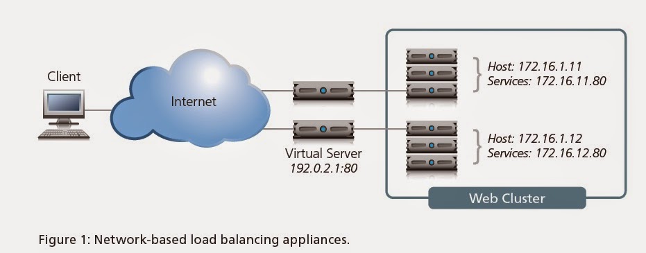
- Packet Flow Diagram
- Load Balancing Basics
- Traffic Distribution Methods
- NAT Functionality
Basic Load Balancing Terminology
Node, Host, Member, and Server
Node, Host -> Physical Server -> Ex 172.16.5.1
Member -> This is referred as service which has combination of IP address and port
Ex: 172.16.5.1:80
Server : Virtual Server (F5 Load balancer)
Pool, Cluster, and Farm
Load balancing allows organizations to distribute inbound traffic across multiple
back-end destinations. It is therefore a necessity to have the concept of a collection
of back-end destinations. Clusters, as we will refer to them herein, although also known as pools or farms, are collections of similar services available on any number of hosts. For instance, all services that offer the company web page would be collected into a cluster called “company web page” and all services that offer e-commerce services would be collected into a cluster called “e-commerce.”
VIRTUAL SERVER:
Virtual server uses single IP address to
represent the server and listening service. Virtual server listens for the
connections initiated by the client, once it received first packet from the
client it translates the destination address from the virtual address to the
node address. The choice of the node is based on the load balancing or
persistence.
Putting It All Together

Packet Flow Diagram


Load Balancing Basics
With this common
vocabulary established, let’s examine the basic load balancing
transaction. As depicted, the load balancer will typically sit in-line
between the client and the hosts that provide the services the client
wants to use. As with most things in load balancing, this is not a rule,
but more of a best practice in a typical deployment. Let’s also assume
that the load balancer is already configured with a virtual server that
points to a cluster consisting of two service points. In this deployment
scenario, it is common for the hosts to have a return route that points
back to the load balancer so that return traffic will be processed
through it on its way back to the client.
The basic load balancing transaction is as follows:
1. The client attempts to connect with the service on the load balancer.
2. The load balancer accepts the connection, and after deciding which host
should receive the connection, changes the destination IP (and possibly port)
to match the service of the selected host (note that the source IP of the client
is not touched).
3. The host accepts the connection and responds back to the original source,
the client, via its default route, the load balancer.
4. The load balancer intercepts the return packet from the host and now changes
the source IP (and possible port) to match the virtual server IP and port, and
forwards the packet back to the client.
5. The client receives the return packet, believing that it came from the virtual
server, and continues the process.
Traffic Distribution methods :
STATIC METHOD:
Ø Round Robin: Client Requests been distributed evenly
across the available servers in the 1:1 ratio.
Ø Ratio:
The ration method distributes the load across available members in the given
proportion. (e.g) if the given proportion is 3:2:1:1 then first server will
receive the 3 packets and 2nd server will receive 2 packets and
other 2 servers will receive one packet to process.
DYNAMIC METHOD:
Fastest:
Load will
be shared across the members based on the response time. The response time has
been computed every second based on the monitoring response time and packet
response time.
Least Connections:
The least
connection mode distributes the load to the members, which has the least connection to process.
Observed:
The
observed load balancing will work based on the system performance. Performance
is the combination of the system response time and the connection count on the
system.
Predictive:
Predictive
is as similar as how observed method. Since the observed method using the
system performance of the current time, predictive method calculates the current load and the before second load.
NAT FUNCTIONALITY:
BIG-IP using NAT in three ways, following
Ø Virtual
Server
Ø Network
Address Translation
Ø Secure
Network Address Translation
VIRTUAL SERVER:
Virtual server uses single IP address to
represent the server and listening service. Virtual server listens for the
connections initiated by the client, once it received first packet from the
client it translates the destination address from the virtual address to the
node address. The choice of the node is based on the load balancing or
persistence.
SNAT:
Unlike virtual servers, SNAT never listen
for connections initiated to the SNAT address. Here when BIG-IP sees the
connection every time it translates the source address from the allowed host
address.
iRules:
iRules is the script which influences the
traffic which flows through the BIG-IP if the script matches for the traffic.
Commonly iRules are used to select the pool to process a client request. This
is technically called as a UNIVERSAL
INSPECTION ENGINE (UIE).
The Load Balancing Decision
Usually at this point, two questions arise: how does the load balancer decide which
host to send the connection to? And what happens if the selected host isn’t working?
Let’s discuss the second question first. What happens if the selected host isn’t
working? The simple answer is that it doesn’t respond to the client request and the
connection attempt eventually times out and fails. This is obviously not a preferred
circumstance, as it doesn’t ensure high availability. That’s why most load balancing
technology includes some level of health monitoring that determines whether a host
is actually available before attempting to send connections to it.
There are multiple levels of health monitoring, each with increasing granularity and focus. A basic monitor would simply PING the host itself. If the host does not respond to PING, it is a good assumption that any services defined on the host are probably down and should be removed from the cluster of available services. Unfortunately, even if the host responds to PING, it doesn’t necessarily mean the service itself is working. Therefore most devices can do “service PINGs” of some kind, ranging from simple TCP connections all the way to interacting with the application via a scripted or intelligent interaction. These higher-level health monitors not only provide greater confidence in the availability of the actual services (as opposed to the host), but they also allow the load balancer to differentiate between multiple services on a single host. The load balancer understands that while one service might be unavailable, other services on the same host might be working just fine and should still be considered as valid destinations for user traffic.
This brings us back to the first question: How does the load balancer decide which host to send a connection request to? Each virtual server has a specific dedicated cluster of services (listing the hosts that offer that service) which makes up the list of possibilities. Additionally, the health monitoring modifies that list to make a list of “currently available” hosts that provide the indicated service. It is this modified list from which the load balancer chooses the host that will receive a new connection. Deciding the exact host depends on the load balancing algorithm associated with that particular cluster. The most common is simple round-robin where the load balancer simply goes down the list starting at the top and allocates each new connection to the next host; when it reaches the bottom of the list, it simply starts again at the top. While this is simple and very predictable, it assumes that all connections will have a similar load and duration on the back-end host, which is not always true. More advanced algorithms use things like current-connection counts, host utilization, and even real-world response times for existing traffic to the host in order to pick the most appropriate host from the available cluster services. Sufficiently advanced load balancing systems will also be able to synthesize health monitoring information with load balancing algorithms to include an understanding of service dependency. This is the case when a single host has multiple services, all of which are necessary to complete the user’s request. A common example
would be in e-commerce situations where a single host will provide both standard HTTP services (port 80) as well as HTTPS (SSL/TLS at port 443). In many of these circumstances, you don’t want a user going to a host that has one service operational, but not the other. In other words, if the HTTPS services should fail on a host, you also want that host’s HTTP service to be taken out of the cluster list of available services. This functionality is increasingly important as HTTP-like services become more differentiated with XML and scripting.
Sunday, 5 April 2020
Tuesday, 17 March 2020

- How do I backup and restore an MDS?
- What is Provider-1?
- How to merge CMA's
- provider-1 problem waiting
- Provider-1 mdsbackup
- Exporting from Provider-1
- Provider-1 NG R55 - Re-Authenticating with SecurID Authentication
- Separating MDS manager from container
- Provider-1 Running Slow
- Provider-1 Global Objects
- MDG Software
- Provider-1 mds_backup no cp.license
- Moving existing management server into PR1
- Logging in Provider1 (NGX)
- Provider-1 backups on SPLAT
- mds_backup vs backup on PR1 (SPLAT)
- Restoring from a backup - compression errors !
- what is CPprofile.sh
- Provider-1 VSX NG AI
- Bridge Mode on VPN-1 NGX
- How to migrate firewall from different CMA?
- Migration from P1's CMA back to Mng Server
- Preconfiguring the IP for CMA on SPLAT
- After in-place upgrade R60A to R61 operations fail on some CMA's
- Provider-1 FWM Process
- Provider-1 and Solaris multipathing?
- How to Fetch logs from VSX?
- cma_migrate error
- Provider-1 Migration
- Problems: P1 R60 trying to manage R61 VPN Pro
- P1 Customer Properties
- Modules intermittently showing "Needs attention"
- Patching PR1 NGX R60 with HFA04
- P-1 R61/NG FP3 SIC issues
- Moving a MDS that is also a CA
- Provider-1: Migration from R60 to R61HFA1
- Provider-1: How to do a fwm sic_reset on a particular CMA?
- Installing a Secondary MDS Manager NGX
- Provider-1 vs. SiteManger-1
- mdsquerydb / cpmiquerybin
- upg/new install from r55 to r61 on new server and use modified cp-admins.C off R55
- cp-gui-clients.C file the same between R55 and R61 ?
- Problems introducing a new remote secondary Provider 1 server (Provider1 NGX R60 HFA0
- Monitoring Provider-1/SiteManager-1 Status
- provider-1 credentials - not passing to SmartDashboard
- securing Provider-1 assets
- Introducing Smartcentre logging server into PR1 NGX
- 2 MLMs defined - how can I confirm syncing ?
- provider1 - bad or good?
- Provider-1 intermittent problems
- CMA migrate
- Provider-1/sitemanager-1
- SIC CMA on Backup Provider
- logging to 2 different CLM versions of Provider-1?
- Provider-1 NGx R65 and licensing issue
- SmartCenter to CMA
- restore
- Provider-1 Global Policy unable to be applied
- How to determine physical IP address of a CMA?
- provider-1 - good/bad thoughts?
- importing policies into CMA
- Provider-1 R65 upgrade from R60
- MDS FWM Process dies
- NGAI VSX cma migration to R61
- unable to login to dashboard after upgrade
- Internal error [11]
- Urgent: Help needed with migrating NGx R65 CMA from Solaris 9 system to SPLAT system
- Urgent help needed with Provider-1 misconfiguration
- Both Provider-1 Managers showing as "active/active"
- Provider-1 NGXR65
- Provider - 1 upgrade R54 to R62
- Provider commands
- Provider-1 with Eventia
- Provider-1
- P-1 problem. need help ASAP
- New CML
- Eventia not generating logf after upgrade from R55 to R61
- LEA Ports to opened for Provider-1
- P-1 and RSA SecurID authentication
- Multiple Standalone FW to 1 CMA
- Error: cannot resolve name!
- Cron MDS Backup for NGX
- GUI for Secureplatform
- migrate users & gui clients
- BACKUP OR MDS_BACKUP?
- Provider installation
- Gateway cluster member doesn't show up in Provider-1 MDG
- P1 HA options
- CMA migration from NGX R60 to R65
- Provider-1 upgrade_export? Is it possible?
- Migrate R55 SC to R65 P1 CMA
- Global policy
- User Provisioning to Provider-1 CMA
- Provider-1 and multi-processor machine
- ¿Provider-1 R62 or R65?
- managing users on a log server that isn't a CLM inside MDS
- mds_backup failed
- Installation failed
- Extracting Administrator Info from P1
- Provider-1 NG R55 to NGx R65 upgrade dilema
- Pre upgrade verifier errors
- Copying objects from CMA to new CMA on same box ?
- Provider-1 NG w/ AI R55 on a Dell 4xCPUs box
- Error to install "global policy" in Provider-1
- Status of network objects (module) in R65 MDS gui
- Provider-1 MLM hardware recommendations
- CHECKPOINT OBJECT REMOVAL
- secondary log server
- R61 to R65 upgrade
- after upgrade to R65 : old folders
- cp_merge could not open the database
- mds backup not synced
- Database Revision Control Houskeeping
- SC to CMA
- Upgrading Provider-1 NGx R65 2.4 kernel to P-1 NGx R65 2.6 kernel
- Import SmartCenter to Pro-1 failed
- a policy push removes rules/objects
- Cannot Create a Log Server in Global Rule Base
- single cma db and policy backup
- R65 - CMA GUI Locks not clearing
- Checkpoint Provider-1 NGx R65 and SMP
- Provider-1 Global mesh Global VPN community with permanent tunnels
- Reasons to move to Provider-1
- CMA to SC: going the other way
- Provider-1 Spec
- difference between CLM and MLM
- Custom commands <NAME> variable
- provider-1 server sizing tool
- CMA Backup
- connectivity issues between the customer cma and its remote-gateway
- cma mirroring error pls help
- provider-1 failover not working help !@!
- Provider R61 to R65 - CMA version issue
- migrating firewall to a different cma
- P1 R65 random CMA stop
- P-1 R65: Read-Only Administrators – Access to Dashboard
- MDS_Restore
- rename Customer
- resuse of ip for clm issues
- Dynamic DNS for Edge in a Provider-1 Environment
- CMA seen with "? Status Unknown" in MDG
- migrate policy and objects
- P1 migration from Solaris to Splat
- Migrating CMAs with VSX objects defined
- Need Procedural Help for setting up P-1
- R65 MDS Central License Fails
- CMA import/cma_migrate. ICA key error
- Failed to read database files.
- Provider1 to Smart centre server
- Auditable (meaningful) permissions from cp-admins.C anyone?
- no Active connections for VSX and R65
- Provider-1 NGx R65 upgrade
- Provider-1 mds_backup and 2GB file size limitation
- FWD 100% on one of CMAs
- CMA reassigning error
- Splitting one SC to many CMA - VS
- Splitting a CMA (provider-1 R65)
- CMA Split best method
- Cannot delete CMA
- Global Policy Database Revision Control Fails
- Question: R70 P1 and R65 VSX upgrades
- Provider-1, unable to add global policy.
- this anoying message after upgrading to NGx R70
- Global policy impact on CMA
- basic Question on global policy
- managment through secondary cma
- Local object "promotion" to global object?
- Upgrading an HA Provider-1 System
- Move to Provider-1
- MLM and CLM License
- Provider-1/Sitemanager-1 product question
- NIC teaming (bonding) is supported on Provider-1 NGx R70?
- Provider-1 migration reccomendations
- Provider-1 New Project
- Problem connecting to Provider-1 with MDG
- Changing the ip address of cma
- Making standby cma active ? (PR1-R60)
- R65 HFA 40 Wont Load on MLM but will on MDS
- Migration and Recovery.
- Provider-1 upgrade Multi-MDS env questions
- R70.1 or R65 with HFA04
- CMA start but MDS could be load
- P-1 to CMA migration.
- SIC is not initialized either at the SmartCenter Server or the peer [error no. 119]
- Weird dynamic objects resolution challenge
- Provider-1 firewall rules required
- Deleted Customer / CMA but directory structure still exists
- CMA disappears after starting
- DELL PowerEdge 2970
- SPLAT Provider-1 NGx R65 upgrade to NGx R70 confusion
- Gateway disconnected
- Provider-1 NGX R65 HFA60 Upgrade Problem
- MDS log_rotate script
- CMA just hung from launching via SmartDashboard
- Smartcentre to P1 Migration
- Provider-1 and VSX ugprade and re-IP address
- Provider-1 R65 backup_util sched error
- HFA70 - Anybody?
- R70.30 Remote File Management
- R70.30 P1 and Odd Behavior with VSX
- Upgrade from P1 R65 to P1 R70 - possible scenarios with VSX R65 gateways
- Provider-1 MDS license
- P1 Upgrade and expansion to HA
- Is it possible to turn on logging on multiple rules in one go?
- cpstat mg on P-1 on R70.30
- No eval license on a new CMA ?
- provider-1 install document
- Import CMA from R65 provider One to R71 Provider One
- Provider-1 CMA migration from R70.40 to R71.10
- Global Object gsnmp-trap causes assignment failure
- P-1 is R70.40 but stand-alone log server is R65 HFA_70
- P1 Inactive Accounts
- CLM design - explanation ?
- Failed to create mirror cma ....
- Provider1 supported under VMware ?
- Provider-1 NGx RR71.20
- Manual CMA import wont start on Provider-1 Splat R65
- P1 Upgrade from R65 to R70
- SPLAT PRO R70.40 and Radius Server
- SPLAT NGx R71.10 on Dell PowerEdge 2650 misery continues
- SPLAT R71.20x on Dell PowerEdge R710 with 12GB RAM
- MDG R70.40 crashes
- SPLAT NGx R71.20 MUST READ
- why am I seeing this message?
- Has Check Point lost all credibility when it comes to software defects?
- Migrate a standalone Smart Center Server to P1 SPLAT
- upgrade P1 from R65 to R70
- in place upgrade from R65 to R71.10 fails
- No logs to CMA after import
- 2 issues
- Multi domain Management (R75) on VMware ESXi 4.1
- Best Practice Guides for Provider-1
- R65 P1 to R75 smart-1 standalone?
- provider-1 trick question sort of
- Not sure if this right, but here goes...additional logging off P-1 to an Eventia....
- [Flows Diagram]
- Unable to install global policy
- CMA : Cannot allocate memory error during policy verification
- SmartDomain Manager GUI quits upon connection
- Provider-1 Connected Administrators - Modify Refresh Rate?
- Policy install fail without detail error
- Perl library for P1 (kind of a scripting question)
- (In)Stability of R71.30 Provider-1
- Upgrade to R75.20 Multi-Domain SecurePlatform on Open Server
- R75 Provider-1 in VMware
- Upgrade to R75.10, with SSDs, from R65; Results
- Unable to "Enable Global Use" on R75.20 SmartDomain Manager
- mds_restore - gzip: stdin: unexpected end of file
- Can't start CMAs FWM stopped
- Migrating a Smart Center with multiple policies to P1
- Provider-1 to new hardware migration
- storage access network
- Global OPSEC application object not seen in CMA
- Merge Rule Base in a CMA
- Provider-1 R65.30 to R75.20 Migrate Error
- Multi Admin roles - User Access Rights in Provider-1
- New R75.20 MLM Server on ESX VM w/SAN Attached Storage
- Question on upgrade_import
- Standalone Security Management Server to Multi-Domain Security Management
- mds_restore failed
- Upgrading MDS from R70.1 to R75.20 with MDS HA.
- Provider-1 and VSX - Migration of a CMA containing VS with change of IP address
- FWM process down after a mds_restore
- Popup when CMA starts
- Unused objects in MDS
- FWM of CMA crashes on policy install after upgrade to R75.30
- admin_for_debug_only default multi-domain super-user account on 75.20?
- Upgrading Provider-1 from R65 to R75.30
- CMA migration from one Provider-1 NGx R70.20 to another Provider-1 NGx R71.30 system
- How to upgrade Check Point Multi-Domain management from R71.20 to R75.30
- How to configure Secondary MDS (MultiDomain Server)...
- all in one SC and Gateway migration to Smartdomain
- P1 MDS and MLM R70.30 to R75.40 Inplace Upgrade
- Log backup/archive scripts MDS / MDLS
- Adding VLAN to VS interface...SmartDomain R75 - issues, advice please
- 10 pound question
- Adding routes with dbedit on VSX and install routes
- MDM R75.40 on GAiA - gotchas
- Import from SmartCenter with multiple policies question
- Database install kills Multi Domain Management GUI on SPLAT R75.40VS
- Newbie question: Adding a existing VSX Cluster to a new domain
- Migrate CLM from old to new hardware
- Gateway Migration to new Provider-1 same CMA
- R75.40 mds_restore is broken
- How to move existing CMAs/MDS to bonded interface
- MLM retore and log file recovery or new MLM install
- Procedure for migrating a CLM to new hardware
- R65.70 CMA to R75.30 CMA
- Advice on migration of multiple Gateways and Provider-1
- Parameters and format for editing queries.conf
- Multiple Policy Import - SDM R75
- What versions of gateways can R75.40 & R75.45 MDS manage?
- Secondary Provider help needed
- Silly question on P-1 installed on a Linux server
- Provider-1 , how to export/import administrators to the secondary Provider-1 server
- Migration of (Globel policy & CMA) Provider-1 to another Provider-1
- MDS Upgradation..
- [SOLVED] R76 MDS / VSX license SmartUpdate Issue
- Clean temporary files in $FWDIR
- MDS migration R71.10 to R76
- smartcenter server configurations to Multi domain security managemnet server
- Purpose of the secondary management server deletion before migrate
- Upgraded R75.2 --> R76 MDS -- Frequent GUI Crashes
- How to find Gateway Status using MDSCMD via CLI
- Missing global rules
- PV1 CMA export-import
- Provider-1 to Smart-1
- Does Checkpoint Provider-1 support LDAP for managing the devices
- Regarding Backup and Snapshot of MDM
- Anti-spoofing configuration
- Migrate Management Server R77 with VSX to MultiDomain R77
- why no backup via sftp?
- Gateways per CMA? Large scale deployment experience?
- SmartDashboard R77.10 crashes on specific CMA when doing "Where used"
- Provider-1 R76 best practices for operational maintenance
- how to make the gateway send logs to the domain server public ip
- Tips to shutdown a SMART-1 50 MDS R75.40 appliance
- New user(Multi Domain super user) not able to login in Multi domain manager & others
- Managing growing filesystem on MDSM (R75.46)- /dev/mapper/vg_splat-lv_current
- MDS (CMAs) <- Static NAT -> MDG
- MDS <-> CP Firewall delay tolerance, MDS <-> MDS delay tolerance
- I have very strange issue. Need help !!!
- How to Move one VSX cluster from one CMA to other CMA.
- threshold_config utility
- Multiple Synchronous Logging Servers (MLMs)
- OPSEC LEA forwarding to Log Rhythm
- Stuck on SmartDashboard loading scree when logging to CMA on Provider 1 version 75.20
- Interesting notes on Jumbo Update and basics
- Building MDS in HA
- Smart1-5 Management server upgrade
- sk103683 - multi domain management server
- AutoBackup with migrtae export or the upgrade_export
- CMA to SMS - Not supported ? HELP
- Backups and or migrate exports for CMAs
- Deleting Secondary MDS and CMA from Primary Multi Doamin Management
- CMA migration fails if any of global objects were ever renamed
- Backup Fails on secondary MDS.
- Need help migrated security policy from one CMA to another
- mds_backup deleting the files it created after upgrade to R77.30
- mds_backup not include customer folder
- vsx_util fails
- CMA Auto Backup
- Not all objects in objects_5_0.C file
- Migrate Provider-1 R75.47 to R80
- Licensing CLM (old name)
- Client Authentication Fails after migrating to CMA
- MDM
- MDS Backup
- Automatic Policy Push
- MDS failed to start after mds_backup in R77.30 with JHFA 205
- DMS Migration issue
- keeping CRL IP after changing IP address of CMA
- Domain Migration with VSX
- Upgrade Provider-1 R77.30 to R80.10 issue (is R80.10 ready for prime time).
- high cpu in clish and confd in Provider-1 R77.30 with JHFA 216
- How to export single domain from MDM to SMS
- Upgrade from R77.30 JHFA 216 to R80.10 not working
- automatic restore of P1 backup
- dbedit rule id syntax
- Error when logging into CLI of Provder-1 server
- CPUSE force install?
- Moving CMA from one MDS env to a different one
- Get VSX objects of a CMA from expert
- MDS R77.30 restore. Some unexpected things.
Subscribe to:
Posts (Atom)

-
PAgP Interaction with Other Features The Dynamic Trunking Protocol (DTP) and the Cisco Discovery Protocol (CDP) send and receive packets...
